
Forum archive
Threads from the old Audio Innovate forum.
Numark M2/M3/M4/DM1050 Innofader Pro Install
All of the listed mixers use the same Numark crossfader with an 8 pin connector. It's nice that Numark standardized on this for many of their older DM series mixers and newer M series mixers.
EDIT 9/23/2015 this is a standard installation for the Innofader Pro2 using adapter (15). Please see below for the wiring of the 3 pin power cable. If you are doing a soldering mod, the order of the power wires does make a difference. No damage will result from reversal, but the channel audio will have much more headroom if the wires are in the correct order. If you can take pics for us showing your installation, please email us your pics.
INNOFADER PRO2 PICS
The key with these pics is to identify the flat side of the cable and the bumpy side of the cable. If you do this first you should easily be able to identify the correct way to hook up the cables.
The wiring is all done by splicing cables and hand twisting. Soldering is helpful for reliability but not required.
NUMARK M2
Special thanks to @LORD.VERM for the following pictures https://linktr.ee/LORDVERM.
OLDER M2 MIXER POWER
This is for older Numark mixers with longer flat cables. If your M2 mixer is a newer version and does not look like the pictures immediately below here, please skip down to "NEWER M2 MIXER POWER"
Please trace through the cables and make sure they are hooked up in the correct order as shown below. If the cables are reversed, the mixer will stop working and make a buzzing sound!
ALSO: make sure the bumpy side of the 3 wire cable is facing up so that your mod matches the picture! If the smooth side is facing up, then make sure you flip over the cable to match the picture!


Make sure to cover all of the wires separately with electrical tape.
This is what the cables look like once tape is put on (thanks to DJ AMAZIN):


Additional pics from Marius Perey. Thanks!


NEWER M2 MIXER POWER
First locate the 3 pin large and 2 pin small cables.
For the 3 pin large cable, you will need to carefully remove all 3 wires from one of the connectors. The below picture just shows one of the wires being removed.
For the 2 pin small cable, you will need to carefully remove the red wire from both of the connectors. The below picture shows how to remove a wire from the small connector.


Please connect the 8 pin crossfader cable from the mixer to adapter (15) as shown in the below picture. Also connect the 8 pin cable on the Numark Pro2 to the crossfader with the C2 cable in series to reduce noise as shown here:
https://www.innofader.com/installations.php?id=84&pid=21
In addition, at the minimum please connect as shown in the "ADAPTER POWER HOOKUP" section. This means soldering 3 wires from the free end of the 3 pin cable you prepared to the PC board in the order as shown, and then plugging into J39. for the free connector, please plug it into J41 to prevent it from touching other parts and short circuiting. Once this is done, you will see that the Innofader Pro2 works, but the Innofader Pro2 will only have an output curve as determined by the CURVE dial.
In order to use the Numark M2 built-in switch to do two different curve settings (mix and sharp), please also add the steps marked "EXTERNAL CURVE CONTROL". These essentially rewire the switch on the M2 directly to the Innofader Pro2 to control the curve settings. Make sure to follow the steps "SOLDER WIRE", "ADD 2 WIRES", and "CUT 2 TRACES". Once you have soldered the red wire, please plug the red wire into the first pin of the 5 pin connector on the main Innofader Pro2 piece. More details in the pictures below:

For the crossfader settings, if you do the EXTERNAL CURVE CONTROL setting, the setting on the crossfader should be in the middle as shown in the below picture. You can adjust it slightly from this position depending on the curve setting you want for a mix curve. The M2 Curve switch will short out the CURVE dial signal so that the Innofader Pro2 works for cutting.

NUMARK M3 MIXER POWER
Please add a 3 wire cable going to adapter (15) to supply power as shown below. Also connect the crossfader cable to the matching connector on adapter (15)

NUMARK M4 - OLDER MIXERS (no SMD)
The following picture shows the wiring for the Numark M4 mixer. The crossfader connector will plug right into J40 on adapter (15) same as shown for the M2 above. For the power cable, simply solder to the PC board as shown on the below picture. Thanks to Jeff Delvalle from Deltronics for helping me with this!

NUMARK M4 - NEWER MIXERS (all SMD)
The following picture shows the wiring for the Numark M4 mixer power supply. For one red wire, make sure it is insulated because you will leave it disconnected. Then solder two other wires to the 7815 IC near the power switch at the back of the mixer as shown below. Otherwise attach the other two connectors as normal, one going to the M4 crossfader cable, and the other going to the Innofader Pro2 crossfader cable.

LEGACY INNOFADER PRO INSTRUCTIONS
Note this is a standard installation for the Innofader Pro. Please check the Numark M series installation drawing for the Innofader Pro: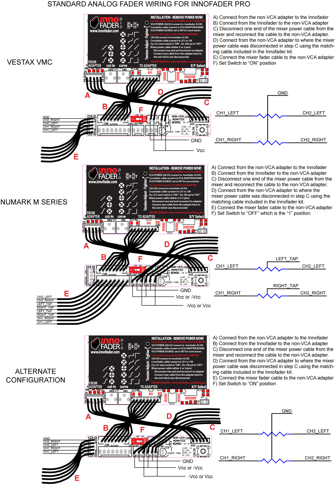
First locate the 3 wire connector on the audio and power supply PC board. In the below picture my finger points to that connector:
If you can't find that connector, you will need to modify the 3 wire cable included in the Innofader Pro kit and solder it as shown below. Note if you do this mod you will only need to hook up to either J36 or J37 but not both.
This is what it looks like on the M3:
Use the non-VCA adapter board adapter from the Innofader Pro kit.
***NOTE to save time, do the installation with the insulated tubing here. The below just illustrates all of the connections.
Referring to the below drawing:
Disconnect cable A from the power PC board and plug it into J36 on the adapter
Plug cable B into both J37 on the adapter and the 3 pin socket where cable A was disconnected
Plug cable C into J5 on the Innofader Pro
Plug cable D into J38 on the adapter
Plug cable E into J25 on the adapter labeled "NUMARK"
Set the mini red switch to the "1" position.
Use the insulated tubing to cover the non-VCA adapter board. Make sure cables C and D come out one end and A, B, and E come out the other end. You can trim the insulated tubing for easier installation; just make sure that the PC board exposed metal parts are covered.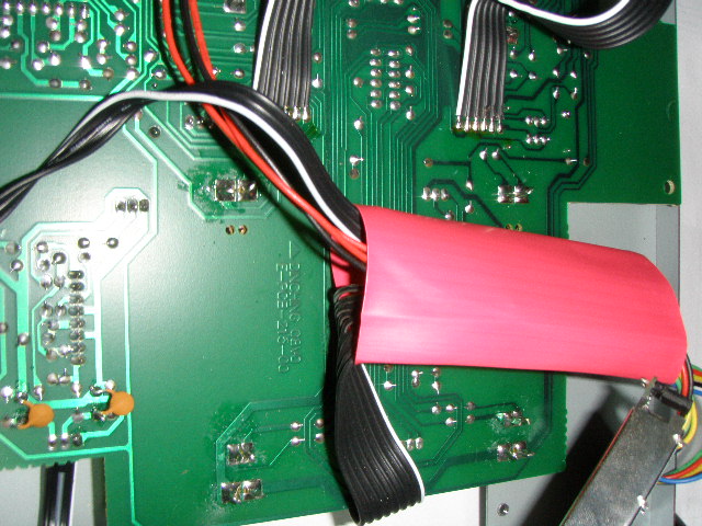
Use 6 self-adhesive washers on each side of the crossfader mounting plate to increase the height.
Install the Innofader wth the label facing the rear.
Replace the faceplate and bottom cover and you're done!