VMC-002 Innofader Pro Noise Fix (Not needed on Red Sticker Pro)
Hello All,
We've heard complaints from customers that there is a high pitched noise on the audio when connecting the Innofader Pro to the Vestax VMC-002 mixer. This noise affects any non-VCA crossfader connection which uses a single DC power supply rather than +/- power supplies so the Numark M series and Technics SH-DJ1200 mixers aren't affected.
This problem is most severe on all first and second revision Innofader Pros. The second revision is indicated by a small green sticker in the upper right corner of the box. Third revision Innofader Pros have a small red sticker in the upper right corner of the box. We recommend for these that you implement just step 15 at the bottom
If you have an Innofader Pro, please skip to "FIXING THE INNOFADER PRO:"
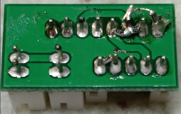
FIXING THE INNOFADER PRO2:
Simply add 4 10k resistors as shown here:
FIXING THE INNOFADER PRO:
If you are finding this issue please write to us at support@audioinnovate.com and we can arrange to do the fix for you free of charge. If you are inclined to do the fix on your end here is how the fix is done:
PARTS NEEDED
soldering iron & solder
30AWG wire or bigger (smaller wire is easier to work with)
Exacto knife
3 47uF electrolytic capacitors rated for 16V or higher
1 0.1uF ceramic capacitor
1 1.2k resistor
4 10k resistors (for optional step below)
The fixes are done to the non-VCA adapter board shown here. This part is included with the Innofader Pro: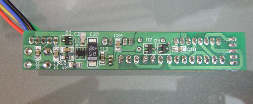
1, 2, 3: Cut these PC board traces using an exacto knife. 1 connects to C34 bottom pin, 2 connects to D2 bottom pin, 3 connects to D3 bottom pin.
4, 5: Use the exacto knife to scrape off the solder mask here and then add solder.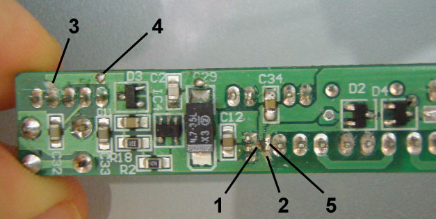
6: Use the exacto knife to scrape off the solder mask here and then add solder.
7: Install one 47uF capacitor with + and - pins as shown. Be careful not to short the top pin to the protruding pin next to C34.
8: Install wire as shown.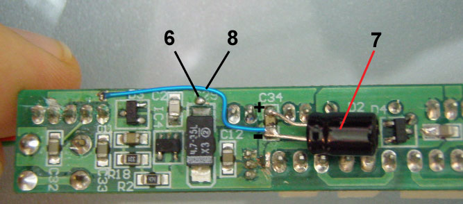
9: Install 1.2k resistor as shown. Make sure one is soldered to the bottom pin of the 3 pin component and the other end is soldered to the exposed solder point created in step 5 above.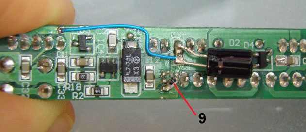
10: Use the exacto knife to cut the traces below and to the right of the bottom right pin of IC4.
11: Install one 47uF capacitor with + and - pins as shown. Be careful to keep solder point created in step 9 above.
12: Make solder connection between the C29 top pin and solder point created in step 6 above. Make sure to keep good contact for the 47uF capacitor installed above in step 11.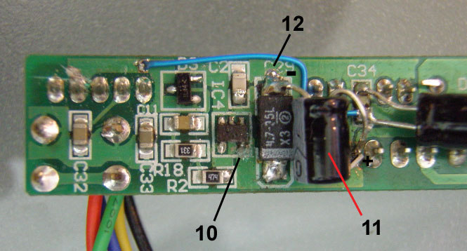
13: Install wire as shown, with the right end connected to the right pin of the 47uF installed in step 11, and the left end connected to the bottom right pin of IC4. Be careful not to short to the surrounding trace that was cut in step 10.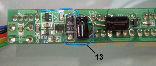
14: Solder a 47uF and a 0.1uF capacitor in parallel with C29. Make sure + and - pins of the 47uF capacitor are as indicated.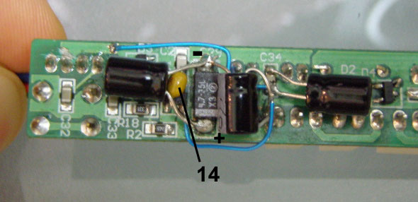
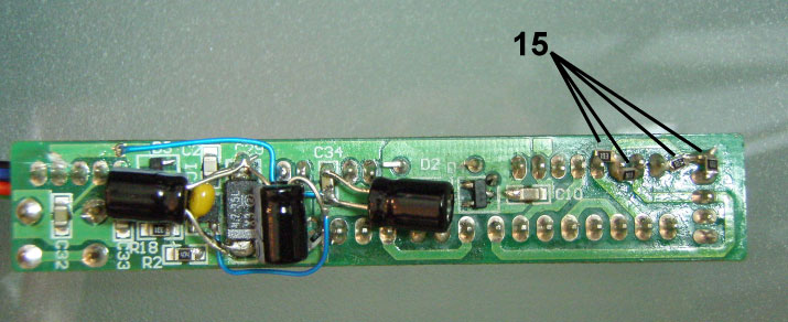
15: OPTIONAL solder 4 10k resistors as shown. Resistor connections are as such, with the 8 pin connector pins 1,2,3,4,5,6,7,8 from left to right and the 5 pin connector pins 1,2,3,4,5 from top to bottom:
1) 8 pin connector pin 5 to pin 6
2) 8 pin connector pin 6 to pin 7
3) 8 pin connector pin 8 to 5 pin connector pin 1
4) 5 pin connector pin 1 to pin 2
Note that this resistor change will further reduce the noise and sharpen the curve but also might result in slightly more sound bleed.