VMC-002 Innofader Pro Install
Updated 9/17/2015
For the Innofader Pro2, simply do the cable connections as shown in Figure 10 here. Otherwise the instructions for assembling and disassembling the mixer are the same as for the Innofader Pro.
This is a standard installation for the Innofader Pro. Please check the Vestax VMC series installation drawing for the Innofader Pro: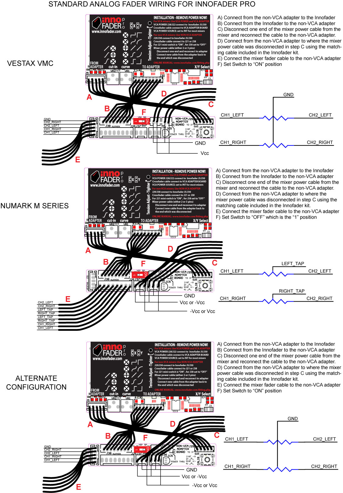
Remove the 2 side brackets and faceplate (4 screws, 2 each side) and bottom cover (8 screws, 2 lower left, 2 lower right, and 4 bottom).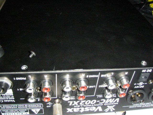
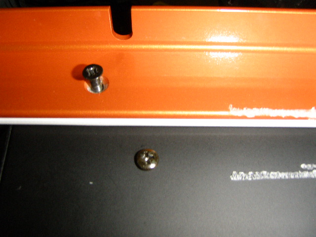
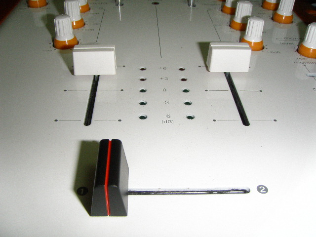
Remove the crossfader.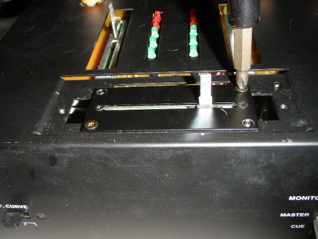
Look at the bottom of unit and locate the 2 pin connector going to the corner of the audio and power PC board.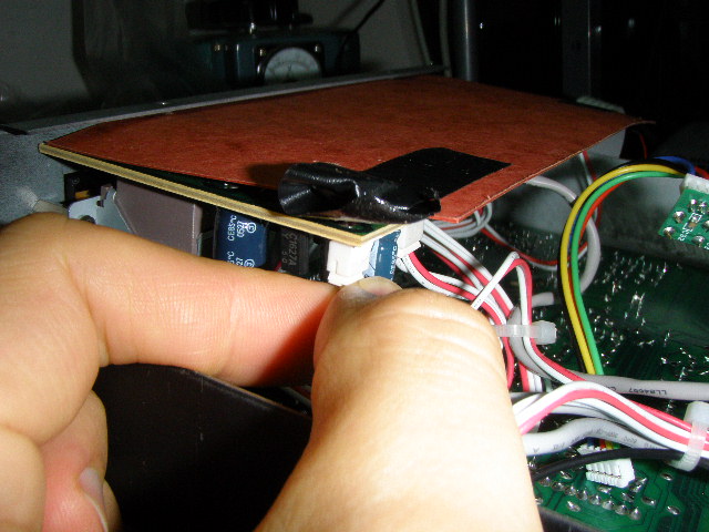
***NOTE: Make sure you remember to include the insulating tube as shown here on a different mixer: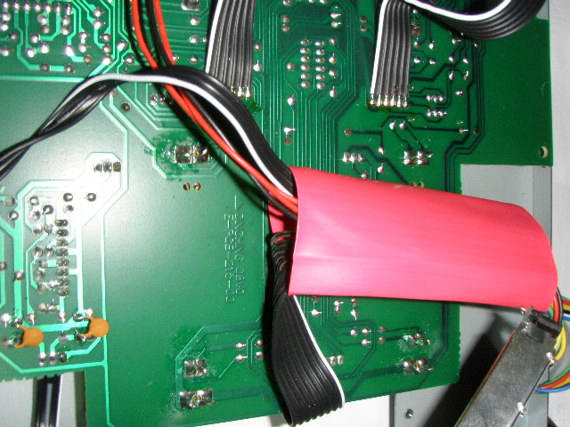
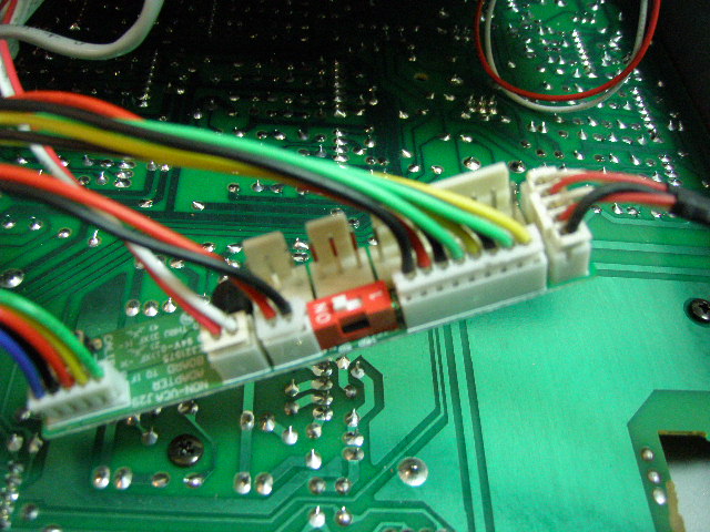
Now for the cable located above, plug it into J13 on the Non-VCA adapter board, and then plug the 2 wire cable included with the Innofader kit both into J12 on the non-VCA adapter board and into the Vestax connector located above. Then connect the 5 wire cable from the non-VCA output adapter board to J5 on the Innofader, connect the 8 wire Innofader cable into J38 on the non-VCA adapter board, and plug the Vestax crossfader connector into the connector marked "Vestax" on the non-VCA adapter.
Note there is a mini switch on the non-VCA adapter board with an "ON" and a "1" position. Make sure it is set to the "ON" position for proper crossfader operation.
As mentioned above, don't forget to include the insulating tube. The pictures are shown without the tube to illustrate the wiring.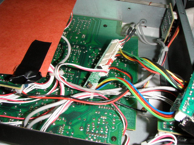
For mounting the Innofader, make sure you use the adapter plate included with the Innofader kit, and make sure the label is facing the front of the unit.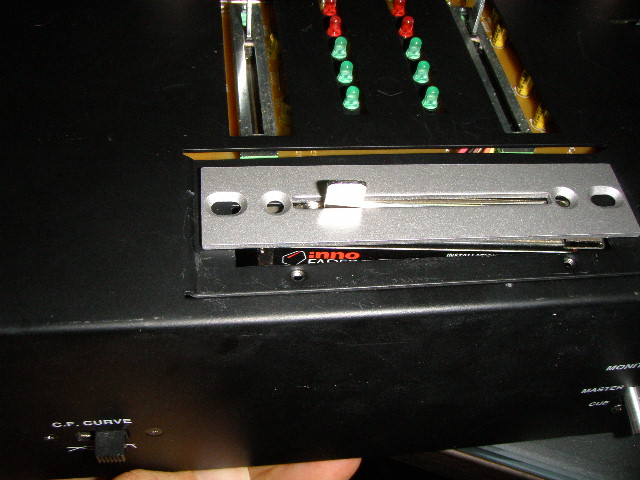
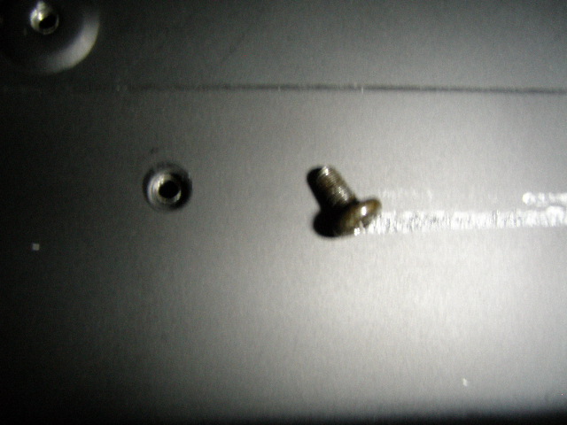
Before putting the bottom cover back together make sure that the insulator card is covering the screw holes to prevent the screws from shorting out.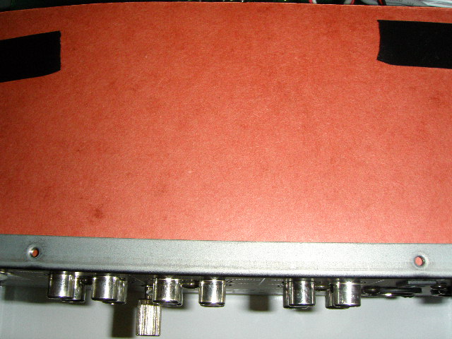
Reassemble the mixer bottom cover 4 short round head screws on the bottom.
Flip the mixer over and make sure that the small round pads surrounding the phono/line switches are installed. They probably fell off when you were working on the mixer.
Use the 4 medium round head screws to finish assembling the bottom cover to the rest of the mixer.
Use the 4 flathead screws to mount the rack mount ears and faceplate together. The rack mount ears go outside of the faceplate. NOTE: If you don't see the mounting holes, swap the 2 rack mount ears.
Place the knob on and you're done!