DJM-400 Installation
mini Innofader PNP P instructions (also applies to mini Innofader Plus)
Thank you to Anthony King for your help with providing the pictures!
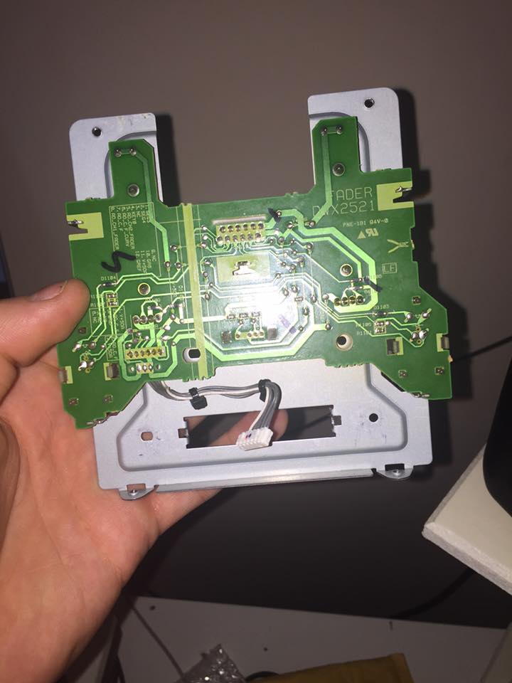
Please refer below to the Innobender Instructions showing how to take apart and put the mixer back together. Inside the mixer there is a plate holding the 3 faders. First remove this plate and remove the original crossfader.
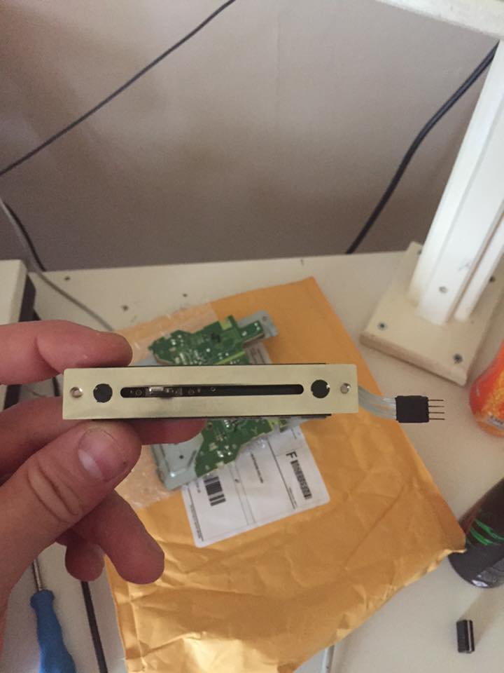
Mount the mini Innofader PNP P to the Pioneer adapter plate included with the kit. Please make sure you use the plastic screws and washers included with the kit as illustrated here.
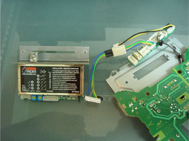
Use the 3 pin adapter cable for hooking up to the mixer crossfader connector. If you align the cable pins with the connector as shown in the below picture - the blue mini Innofader PNP P wire lines up with the white DJM-400 wire - then the mini Innofader PNP P will have a green light during the test mode, and it will work immediately once you pull the switch down.
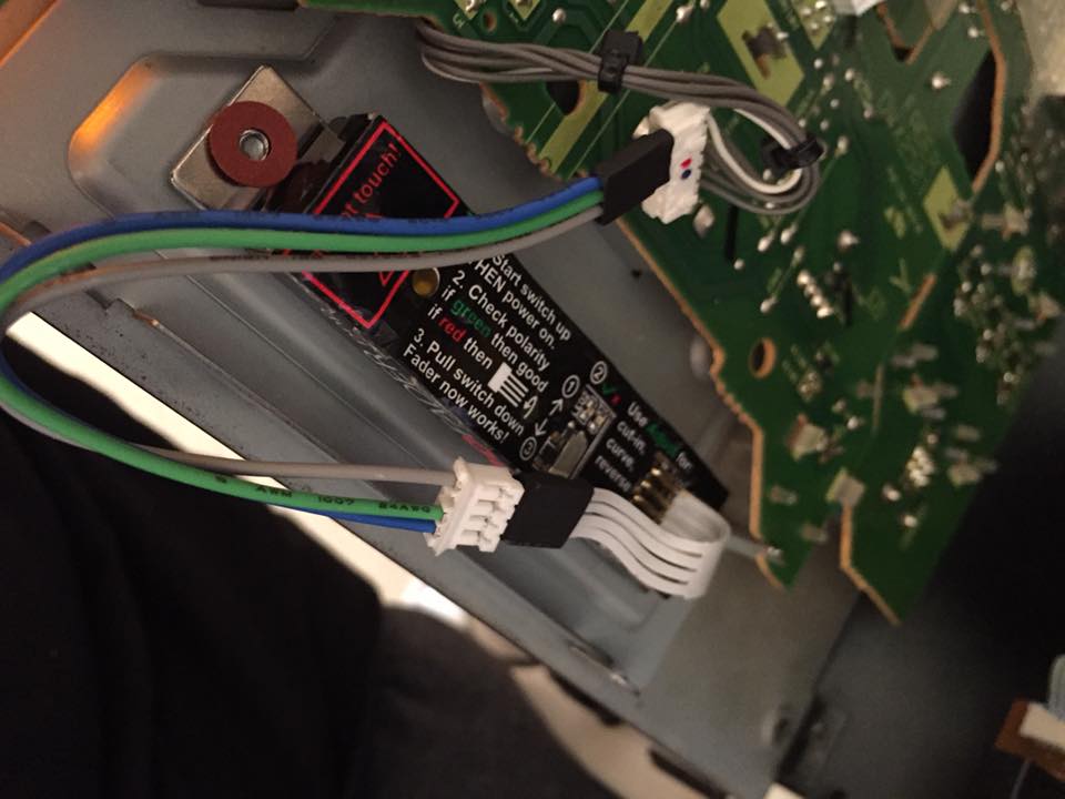
When you install the mini Innofader PNP P it will look something like this. ***Note in the picture the plastic screws are shown for mounting the mini Innofader PNP P to the fader plate. This is not needed because the mini Innofader PNP P mounted to the Pioneer plate is already isolated
-------------------------------------------------------------------------------------------------------------------------------------------
Innobender instructions
NOTE: Our most recent Innobender version does not come with any adapter boards. It comes with adapter cables instead. The 3 pin small adapter cable connects to 3 pins on the Pioneer connector. Please follow the instructions included with the Innobender kit for connecting the DJM 400.
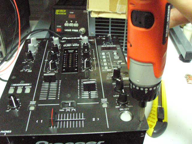
First to start remove the screws as shown here. Note that the next few pictures have the Innofader at the crossfader; on the DJM-400 it will have the original fader installed. Sorry I was lazy here. Bear with me. 
Once you remove all of the faceplate screws, you should be able to pop off the faceplate. Lift up the faceplate slightly and remove the flat cable shown here: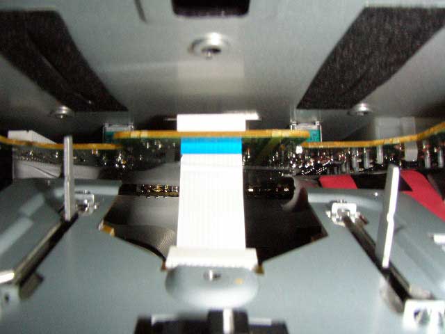
For ease of installation, lift the faceplate up, flip over to the left, and place down as shown here: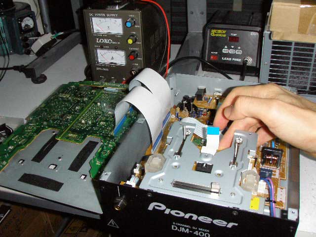
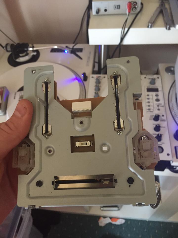
Remove the 2 screws on the front panel shown here. The crossfader plate should then drop down. Also make sure to disassemble the crossfader from the fader plate by removing the 2 mounting screws. All of the screws you need to remove here have red circles around them.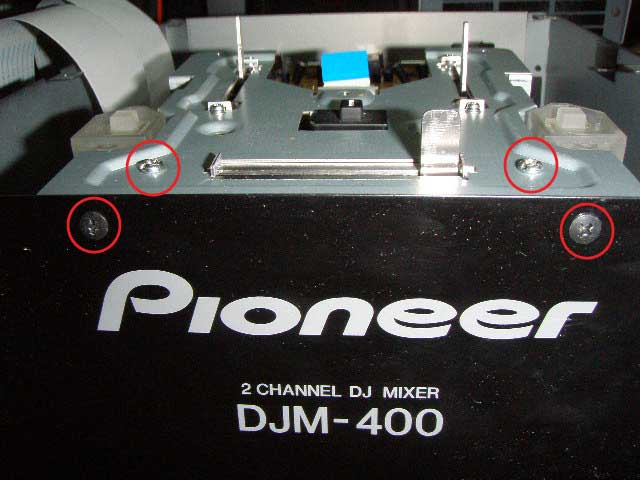
Before mounting the Innofader, prepare it as below. First mount the Innofader to the large bracket using the 6mm insulated flathead screws and insulated washers. Please read the instructions for insulating the Innofader from the mixer first.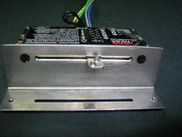
Mount the tab to the Innofader with the 2 hex screws and 2 lock washers. Use a 2.5mm hex wrench to tighten the screws. While you are installing these screws, hold the Innofader body as shown in the picture. This will maximize the distance between the top screw and the bracket and eliminate any potential rubbing.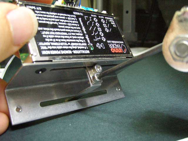
Connect the 6-pin crossfader cable to the Misc Adapter Board connecter J13 "NUMARK DIGITAL". Note the connector housing is already removed because the Pioneer cable header won't fit. This is completely normal and a special modification we did just for this product. Install the crossfader cable with the white wire closest to the blue Innofader cable wire.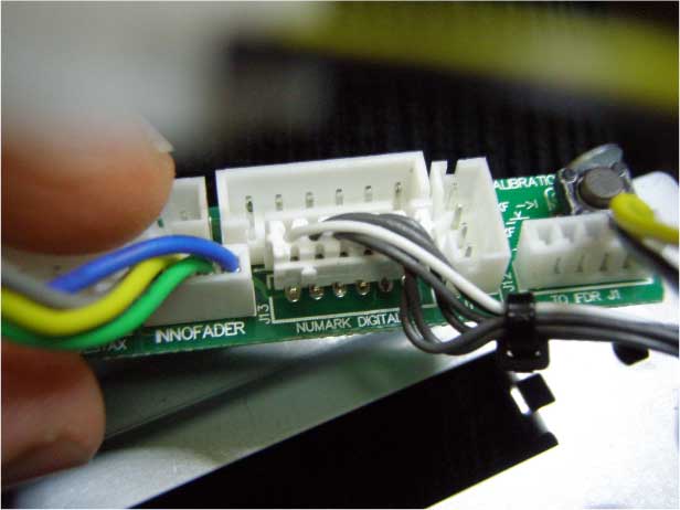
Disconnect the Innofader cable from the Innofader itself and connect to the Misc Adapter Board. As shown in the picture, the misc adapter board blue wire goes to the Innofader grey wire and vice versa. But the green wires and yellow wires still match.
****NOTE: There is a batch of Innofaders which have the holes drilled upside down. In this case when you assemble the Innofader to the plate as shown in this picture, the label will be facing down rather than up.
If the label is facing up, the wire connections between the Innofader cable and adapter board are as follows:
BLUE <-> GREY
GREEN <-> GREEN
YELLOW <-> YELLOW
GREY <-> BLUE
If the label is facing down, the wire connections between the Innofader cable and adapter board are as follows:
BLUE <-> GREY
GREEN <-> YELLOW
YELLOW <-> GREEN
GREY <-> BLUE
We released a small number of faders with the label facing down where the green and yellow wires are swapped. If this is the case, please use the mini-screwdriver included with the Innofader to swap these wires as shown here (different connector but same idea)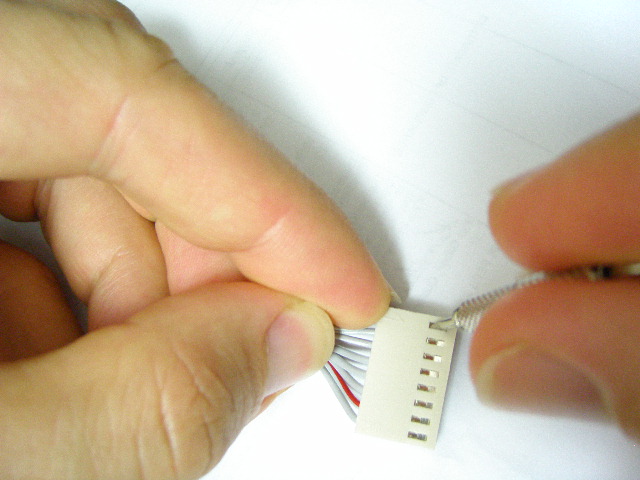
Place the Insulator tube over the Misc Adapter board and Innofader cable, and connect the Innofader cable back to the Innofader.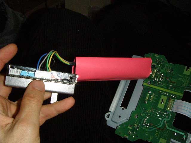
Place the Innofader with the bracket in the correct position on the Pioneer fader plate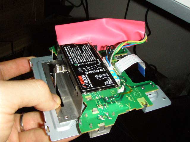
Screw the Innofader with the bracket down to the Pioneer fader plate using the 8mm flathead screws included with the Innofader. Plug the flat cable back into the fader plate PC board. Make sure you tape down the insulator securely to keep a safe distance from power supply components in the Pioneer DJM-400. Note I was a bit lazy in this picture. Use more tape to be safe!!!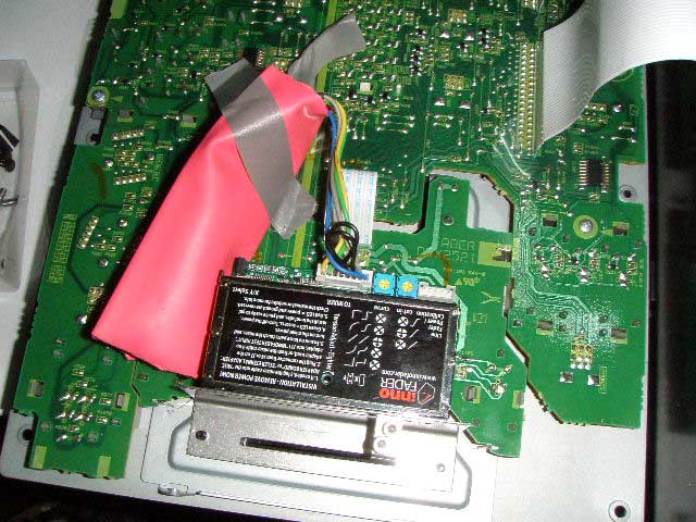
Put the faceplate back on the mixer and screw the front panel screws back into the fader plate. Note the drawing shows the screws only partially installed; make sure later to fully tighten the screws.
Screw the faceplate screws back into the fader plate. Note the drawing shows the screws only partially installed; make sure later to fully tighten the screws.
Finally install the remaining faceplate screws
And you're done!